상품상세정보
 |
 |
 |
 |
 |
 |
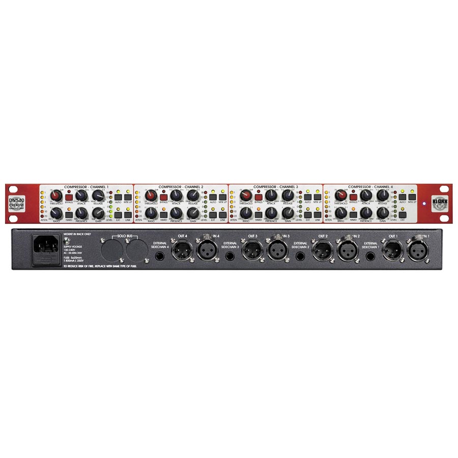
DN540 Quad Compressor
Compressors were originally devised to reduce the dynamic range of audio signals. To do this they use gain modification that makes adjustments to signal levels automatically, dependant on the level and dynamic of the signal itself, and upon the character and control settings of the particular compressor unit.
Throughout the history of dynamics processing many different types of compressor have been produced using many different types of gain technology. Each type has a distinctive sound. Users have found many applications which benefit from these often unintentional compression audio artifacts, taking the use of compressors far beyond simple dynamic range reduction, sometimes even generating the complete reverse; dynamic enhancement. It is with these creative applications in mind, that the DN540 has been designed to offer a latency-free, comprehensive and compact dynamics processing package.
With its unique presence feature the DN540 will be especially useful on vocals to eliminate the "pumping" effects of spill and to add "air" to the sound without introducing noise.

- Quad channel compressor
- Easy to use and requires minimum set up to produce excellent results
- Features a unique and intuitive presence control that improves the high frequency sound quality without increasing noise or squealing (howl-round)
- Features extremely low noise and distortion levels
- Designed from a sonic point of view and can produce extremely transparent compression
- Advanced envelope generator with manual controls that can be easily switched in or out to produce transparency or creative dynamic effects
- The compressors intuitive turn it up, turn it down approach to control knob labeling avoids confusion during fast adjustment
- The status of bypass, solo and other major switches are boldly presented to avoid mistakes
- Linking features true power summing so it always provides true threshold setting for stereo material
- Great sounding compressor as it has been "tuned" by ear
- Road worthy chassis
- Balanced outputs
- Auto switching power supply
- 1U
DN540 Architect's & Engineers Specification
The Compressor shall provide four (4) complete channels of creative presence-accentuating compression in a standard 1U 19" rack mount chassis. Each channel shall have an electronically-balanced input and output on 3-pin XLR connectors.
Each channel shall have a rotary Threshold control to set the signal level at which the Compressor applies compression and a rotary Ratio control to set the amount of compression applied above the set threshold.
Each channel shall have rotary controls for setting the Attack and Release times of the Compressor. Each channel shall have a latching pushbutton switch with an associated green LED labelled "AUTO" to select rms-sensing Auto compression mode instead of the default peak-sensing Manual compression mode. In Auto compression mode the Attack and Release rotary controls shall be disabled.
Each channel shall have a rotary Presence control to dynamically accentuate a broad range of frequencies centred around 5 kHz. The purpose of this function shall be to allow high-mid frequency content often lost when compression is applied to be retained.
Each channel shall have a rotary Gain control to apply make-up gain to the Compressor.
Each channel shall have a latching pushbutton switch with an associated orange LED labelled "HARD" to change the compression characteristic from the default soft knee setting to a hard knee setting.
Each channel shall have a latching pushbutton switch with an associated red LED labelled "BYPASS" to remove the Compressor from the signal path.
Each channel shall have a six (6) segment attenuation meter to show the amount of gain reduction being applied by the Compressor.
Each channel shall have a six (6) segment signal level meter which by default shall show the compressor output signal level. A latching pushbutton switch shall be included on each channel with a green LED labelled "MTR I/P" to select input level metering instead.
Each channel shall have a latching pushbutton switch with an associated yellow LED labelled "EXT" to select the external sidechain ¼" TRS Jack input as the signal source for the Compressor sidechain instead of the signal that the Compressor is acting on.
The Compressor shall have a channel link facility whereby adjacent channels can have their sidechains summed with the left-handmost channel acting as the master control. Channels 1-3 shall have a latching pushbutton switch with an associated yellow LED labelled "LINK" to allow linking to the adjacent right-hand channel. The presence and gain controls shall remain independent when the channel linking facility is enabled.
The Compressor shall meet or exceed the following specifications:
Distortion: 0.05% (1kHz 0dBu)
Dynamic
range: 116dB (20Hz-20kHz
unweighted)
Frequency response: ±0.5dB (20Hz-20kHz relative to
1kHz)
Noise floor: -94dBu (20Hz-20kHz
unweighted)
Attack time: 0.1ms-20ms
Release
time: 50ms-2
secs
Maximum output level: +22dBu into 600 ohms
The Compressor shall have an integral switch-mode power supply capable of operating from a 100 - 240 V a.c. ±10%, 50 to 60 Hz AC power source and have an IEC 60320 C14 mains inlet with integral fuse. A blue LED labelled "POWER" shall be included on the front panel to indicate when the unit is powered on.
The Compressor shall be the KLARK TEKNIK Model DN540 and no alternative specification option is available.
DN540 Architect's & Engineers Specification
Inputs
- Four
Type: Analogue, electronically balanced female XLRs (Pin 2
hot)
Impedance: 10kΩ
Maximum input level: +22dBu
Common mode rejection:
Typically, -80dB at 1kHz
Outputs
- Four
Type: Analogue, electronically balanced male XLRs (Pin 2
hot)
Signal drive capability: <600Ω
Output impedance:
<60Ω
Maximum output level: +22dBu
EXT
inputs - Four
Type: Analogue, electronically balanced Jack
sockets
Impedance: 20kΩ
Maximum input level: +22dBu
Common mode
rejection: Typically -60dB at 1kHz
Performance
Maximum
signal level any input or output: +22dBu
Frequency response: ±0.5dBu (input
to output), 20Hz to 20kHz
Dynamic range: >116dB (22Hz to 22kHz
unweighted)
Noise at main output with unity gain: -94dBu
Distortion at
1kHz 0dBu with steady unity gain condition: <0.05%
Signal delay: 0
seconds
Compressor
Threshold
scale: -50dB to +25dB
Ratio scale: Minus infinity (-4):1 to 1:1
Attack
scale: 0.1s to 20ms
Release scale: 50ms to 2s
Presence scale: Minimum
(flat) to maximum (-3dB at 5kHz)
Gain scale: 0dB to 18dB
Terminations
Audio:
3-pin XLRs (male and female) and 1/4" TRS balanced Jack sockets
Power: 3-pin
IEC
Power
Requirements
Voltage: 100VAC to 240VAC ±10%
Frequency: 50Hz to
60Hz
Consumption: <25W
Dimensions
Height:
44.5 mm (1.75"), 1U high
Width: 483 mm (19")
Depth: 305 mm (12")
Weight
Net:
4.6 kg
Shipping: 5.6 kg
Operation
Temperature:
+5°C to +40°C
Storage
Temperature:
-20°C to +60°C
Due to a policy of continual improvement, KLARK TEKNIK reserves the right to alter the function or specification at any time without notice.

관련 상품


배송안내
|
| ||||||||||||||||||||||||||||||||||||||||||||||||||||||||||||||
교환 및 반품안내
|
||||||||||||||||||||||||||||||||||||


이미지 확대보기DN540


비밀번호 인증
글 작성시 설정한 비밀번호를 입력해 주세요.
장바구니 담기
상품이 장바구니에 담겼습니다.
바로 확인하시겠습니까?
찜 리스트 담기
상품이 찜 리스트에 담겼습니다.
바로 확인하시겠습니까?

평일 오전 9:00 ~ 오후 6:50
토요일 오전 9:00 ~ 오후 3:00
은행 : 국민은행
예금주 : 이정석